
Views: 0 Author: Site Editor Publish Time: 2026-10-08 Origin: Site


A secure electrical connection serves as the vital heartbeat of any commercial or industrial power system. Even a microscopic gap or misalignment within a termination can trigger immediate, catastrophic failures. Improper selection or faulty installation of a Cable Lug remains a leading cause of severe electrical resistance, thermal runaway, and crippling system downtime. Engineers and electrical contractors frequently underestimate the immense mechanical and thermal forces acting upon these unseen connection points. When these crucial components fail, entire facilities can lose power in seconds. This definitive guide equips procurement teams and installers with the technical knowledge necessary to evaluate, select, and properly terminate these devices. You will discover strict performance baselines, essential material science principles, and proven compliance standards. Ultimately, you will learn how to guarantee flawless execution and absolute safety in your next electrical project.
Material compatibility between the cable and the lug is non-negotiable to prevent galvanic corrosion (e.g., requiring bi-metallic lugs for dissimilar metals).
Correct sizing must account for both the conductor cross-section (AWG/mm²) and the terminal stud size to ensure a flush, low-resistance connection.
Installation integrity relies heavily on matched crimping tools and dies; improper crimping profiles void UL/IEC certifications and introduce severe fire risks.
Electrical reliability heavily depends on terminal connections. We define the success of a high-quality Cable Lug by two strict criteria. First, it must provide an unyielding mechanical grip on the conductor. It must withstand pulling, bending, and continuous vibration. Second, it must maintain near-zero electrical resistance across the joint. When you compromise on either factor, the entire electrical system faces imminent failure.
The cost of failure extends far beyond a simple component swap. Poor terminations trigger a dangerous cascading effect across the infrastructure. Initially, localized heating begins at the compromised connection point. This heating causes subtle voltage drops across the circuit, forcing equipment to work harder. Over time, these thermal cycles cause the metal to expand and contract. This movement loosens the connection further. Arc flash risks increase dramatically, threatening personnel safety with explosive energy releases. Facility managers also face immediate non-compliance penalties regarding local fire and safety codes.
Manufacturers must design these parts to meet strict regulatory baselines. For commercial and industrial environments, components must satisfy UL 486A-486B standards. This standard dictates strict pull-out force and temperature rise limits. Global applications often require IEC 61238 certification, ensuring reliable performance under heavy load cycling. Furthermore, RoHS compliance ensures the materials remain free from hazardous substances like lead. Meeting these critical baselines guarantees the connector will perform safely under intense and unpredictable electrical loads.
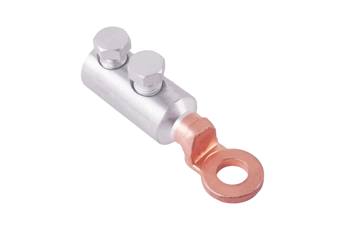
Different environments demand specific termination styles. You must match the connector geometry to your mechanical layout and maintenance needs. Using the wrong form factor introduces unnecessary mechanical strain.
Ring lugs offer maximum security for most standard industrial connections. They feature a circular palm that fully encloses the terminal stud. This closed-loop design makes them the best choice for high-vibration environments like marine engine rooms or heavy manufacturing floors. If a terminal nut loosens slightly, the wire will not detach. However, installing them requires complete stud removal, which adds time during initial setup.
Fork or spade lugs feature an open-ended, U-shaped design. They are ideal for rapid installation scenarios. You can easily slide them under captive-screw terminal blocks without removing the screw entirely. This allows maintenance teams to work much faster during panel upgrades. Because they lack a closed loop, they remain inherently less secure. We do not recommend them for environments experiencing continuous heavy vibration.
Tubular lugs feature a robust, seamless copper barrel design. We use them extensively for heavy-duty applications. They excel in main power distribution panels, transformer connections, and heavy grounding systems. Their thick barrel walls handle high mechanical stress and intense crimping forces effortlessly.
Pin lugs solve unique spatial and geometric challenges. They help you terminate extremely thick cables into smaller contact blocks. You frequently see them used with modern circuit breakers and compact contactors. The slender, solid pin fits easily into cramped housing spaces, while the wider barrel accepts a large-gauge wire safely.
You must decide when an application requires heavy-duty components over standard ones. Use this simple framework to evaluate your specific needs:
Mechanical Stress: Upgrade if the cable undergoes constant movement, pulling forces, or severe vibration.
Amperage Requirements: Choose heavy-duty options for sustained, high-current fault conditions where heat dissipation is critical.
Environmental Exposure: Thicker walls withstand corrosive industrial atmospheres, chemical fumes, and salt spray better than standard gauges.
Standard gauge components work perfectly well for protected, static panels indoors. However, heavy-duty variants offer vital insurance for demanding, unpredictable field installations.
Material science dictates how long your termination will survive in the real world. You must select metals that balance pure electrical conductivity with long-term environmental durability.
Standard electrolytic copper offers exceptional electrical performance. Manufacturers typically use highly conductive pure copper as the base material. However, bare copper oxidizes rapidly when exposed to ambient air. This natural oxidation forms a restrictive layer that drastically increases electrical resistance. To solve this, electro-tin plating serves as a universal industry standard. The micron-thin tin coating prevents surface oxidation completely. It helps the Cable Lug endure highly corrosive environments, moisture, and chemical exposure for decades.
Aluminum lugs provide significant weight reduction for large-scale projects. They also present distinct cost advantages over copper equivalents. Utility companies rely on them heavily for long-distance overhead power distribution. But aluminum poses a unique installation challenge. It forms a tough, non-conductive oxide layer almost instantly upon exposure to air. You must apply specialized joint compounds during installation. Installers vigorously wire-brush the conductor and apply anti-oxidation pastes. These pastes break down the oxide layer and seal the final connection from atmospheric moisture.
Connecting dissimilar metals creates severe electrical problems. If you attach an aluminum cable directly to a copper busbar, galvanic corrosion occurs. This electrochemical reaction destroys the joint over time, especially in humid environments. Friction-welded bi-metallic (Cu-Al) lugs provide the definitive engineering solution. Manufacturers use intense rotational friction to fuse an aluminum barrel directly to a solid copper palm. When evaluating these bi-metallic parts, scrutinize the weld integrity carefully. A high-quality weld should show zero surface porosity. It must withstand extreme bending forces without cracking or separating at the fused seam.
Selecting the correct size requires absolute precision. You cannot guess wire gauges or estimate terminal stud dimensions. A poor fit guarantees failure.
Proper conductor sizing goes far beyond reading the label on a spool. You must match the inner diameter of the barrel to the specific wire gauge accurately. This process changes depending on whether your project uses AWG (American Wire Gauge) or metric (mm²) measurements. Stranding type also alters the required barrel volume. Solid wires fit differently than heavily stranded flexible cables. Welding cables, for instance, utilize hundreds of hair-thin strands. They often require larger barrels or flared entries to accommodate their unique physical volume.
Cable Sizing and Stranding Comparison Chart
Stranding Type | Flexibility Profile | Common Application Scenario | Barrel Design Requirement |
|---|---|---|---|
Solid Conductor | Rigid / Stiff | Basic commercial building wiring | Standard inner diameter (snug fit) |
Standard Stranded | Moderate Flexibility | Industrial control panels | Standard inner diameter |
Fine Stranded (Welding Cable) | High Flexibility | Moving machinery and robotics | Flared entry or oversized barrel |
Exact stud hole sizing remains equally crucial for safety. If you place a connector with a 12mm hole onto an 8mm terminal stud, you drastically reduce the physical contact area. This physical mismatch leads directly to micro-arcing and rapid, uncontrollable overheating. Always match the bolt size precisely to the connector palm to maximize the conductive surface area.
Smart buyers actively look for specific inspection features. Inspection windows (small holes near the palm) allow installers to verify proper wire insertion depth before initiating the crimp. Flared entries help you guide finely stranded wires smoothly into the barrel without snagging, bending, or fraying individual strands.
When shortlisting vendors, use a strict evaluation checklist to ensure quality control. Demand complete material traceability back to the raw metal source. Ask for routine batch testing reports detailing pull strength and conductivity metrics. Verify all UL and IEC compliance documentation independently. Finally, ensure the vendor provides a fully compatible tooling ecosystem designed specifically for their proprietary connectors.
A perfectly manufactured connector will fail instantly if installed incorrectly. Modern electrical standards mandate strict, repeatable installation protocols.
The industry clearly favors crimping over soldering for high-current and high-voltage applications. Crimping provides unmatched mechanical consistency across thousands of connections. When done correctly, it creates a solid, cold-welded joint between the copper wire and the barrel. Soldering introduces a dangerous fundamental flaw. If the joint experiences an unexpected thermal event or short circuit, the solder can melt. This melting causes catastrophic mechanical separation and massive electrical arcing. Crimping eliminates this thermal solder-melt risk entirely.
Tooling compatibility dictates your overall installation integrity. You must use the manufacturer-specified crimping tool and the correct die profile. Different components require specific die shapes to compress the metal properly. Common industry profiles include Hex crimps, Indent crimps, and W-crimp designs. Hex crimps apply uniform pressure from all sides, making them ideal for standard stranded copper. Indent crimps work exceptionally well for fine-stranded cables. Using a generic, mismatched tool on a specialized Cable Lug voids all safety certifications instantly.
Field installers must recognize common installation defects immediately.
Over-crimping: Applying excessive hydraulic force crushes the internal components. It severely damages delicate wire strands and frequently fractures the outer barrel. Fractures expose bare copper to corrosive atmospheric elements.
Under-crimping: Applying insufficient force leaves microscopic air gaps inside the barrel. These invisible gaps create high electrical resistance. They also introduce severe wire pull-out risks during normal operational vibration.
Robust quality assurance protocols prevent these hidden failures from reaching the field. Engineers routinely perform mechanical pull-testing on sample batches to verify grip strength against established industry tables. Post-installation visual inspections remain absolutely essential. Inspectors look for a smooth, uniform crimp profile. They verify wire visibility through the inspection window. They also check for any sharp metal flash extruded during the crimping process, which indicates a mismatched die.
Choosing the right electrical connector is a precise engineering decision, not a casual afterthought. You must constantly balance complex material science with exact mechanical fit. Strict adherence to regulatory compliance ensures long-term operational safety. A mismatched component, an ignored galvanic reaction, or a faulty crimp can bring an entire industrial operation to a sudden, costly halt.
We encourage you to audit your current termination practices immediately. Review your existing hardware inventory and field installation tools for compatibility. Download technical specification sheets for your most common wire gauges and environments. Always request physical manufacturer samples to verify physical tolerances before committing to bulk procurement. Taking these proactive steps ensures your electrical systems remain safe, efficient, and fiercely reliable.
A: No. Connecting a copper lug directly to an aluminum wire causes severe galvanic corrosion. The resulting chemical reaction rapidly degrades the connection, leading to high electrical resistance and potential fire hazards. You must use a bi-metallic (Cu-Al) lug designed specifically to bridge these two dissimilar metals safely.
A: Heavy-duty lugs feature significantly thicker wall construction. This added thickness provides superior structural integrity under high mechanical stress and intense vibration. It also allows the component to handle massive fault-current surges without melting or distorting, making it ideal for harsh industrial environments.
A: A proper crimp exhibits clear visual markers. The inserted wire should be clearly visible through the inspection hole. The crimped barrel must show correct, uniform die stamp markings. It should possess no sharp metal flash or barrel fractures. Mechanically, the joint must meet or exceed strict industry pull-test values.
A: The impact of a thin tin layer on overall electrical conductivity is virtually negligible. However, its protective benefits are enormous. Electro-tin plating prevents rapid surface oxidation and shields the underlying copper from corrosive elements. This protection ensures the connector maintains stable, low electrical resistance throughout its entire operational lifespan.
