
Views: 125 Author: Stephen Liu Publish Time: 2026-09-05 Origin: Site


A C type copper wire clamp for grounding should be selected as part of a complete connection system, not as an isolated piece of hardware. Start by confirming the conductor arrangement, intended grounding or bonding function, joint location, approved tooling, environmental exposure, and required evidence. Then select and install the clamp against controlled project documents.
MINGXU lists its CCT C-Type Copper Wire Clamp for grounding, bonding, and conductor joining. Those verified uses establish the product family’s role, but they do not replace project-specific engineering. The applicable conductor combination, installation method, and acceptance criteria should come from approved drawings and supplier documentation for the exact item ordered.
The most important design objective is continuity that remains mechanically stable and inspectable over time. A low reading taken once can be useful, yet it says little about whether the joint is correctly identified, protected from its environment, or able to withstand future disturbance.
A grounding or bonding connection has several jobs at once. It must maintain an intentional conductive path, hold the conductors in the specified geometry, resist unwanted movement, and remain compatible with the surrounding installation. A successful joint balances all of these outcomes rather than optimizing only one.
For design reviews, separate the required function into three questions:
Is the connection part of grounding, equipotential bonding, or a general conductor joint?
Does it connect a continuous main conductor, create a branch, or complete an equipment bond?
Must the finished joint remain visible, or will it be enclosed or otherwise difficult to access?
These distinctions shape the documentation and inspection plan. A concealed branch, for example, needs stronger installation records because later visual confirmation may be impossible. An accessible bond may justify periodic checks, but access alone does not compensate for an uncontrolled installation.
Grounding connects a defined part of the electrical installation to the grounding arrangement specified by the project. Bonding connects conductive parts so that potential differences are controlled. Conductor joining creates electrical continuity between conductors, but the joint’s system purpose still needs to be stated.
Using one vague label for all three can cause procurement errors. The bill of materials should identify the system function and the conductor arrangement, not simply request “ground clamps.” This gives suppliers and reviewers enough context to flag an unsuitable assumption before material reaches the site.
A common mistake is to choose a clamp because its shape resembles an existing part. Visual similarity does not prove suitability. Begin with documented conductor information and the approved connection detail, then verify that the proposed CCT item matches those requirements.
Record the following in the technical request:
Conductor material and construction as shown in project documents.
Main and branch conductor identification.
The nominal conductor information required by the approved design.
Joint orientation, available working envelope, and nearby obstacles.
Whether the connection will remain accessible after completion.
Required supplier drawing, installation instruction, and inspection record.
This approach deliberately avoids guessing from a photograph or model name. MINGXU identifies CCT as a C-Type Copper Wire Clamp and states its use in grounding, bonding, and conductor connections; any additional performance detail should be confirmed for the ordered configuration.
A C-shaped connector works through a defined relationship between connector body, conductors, and installation process. The engineer should review how conductors sit in the connector, whether the branch approaches without forced bending, and whether installation tools can be positioned correctly.
Do not treat nearby cable routing as a separate issue. If a conductor must be pulled sideways to enter the clamp, that routing can introduce persistent mechanical load. Correct the route or support arrangement rather than asking the connector to hold an unintended strain.
A useful specification is a decision record. It tells the buyer what must be supplied, the installer what must be controlled, and the inspector what evidence demonstrates completion. It should distinguish verified product facts from project requirements and requested supplier evidence.
Include these minimum document requirements:
Exact manufacturer and model designation on the offer and packing list.
Product drawing for the proposed conductor combination.
Installation instruction identifying the approved tool system and sequence.
Material declaration relevant to the proposed connection and environment.
Batch or shipment identification that can be linked to site records.
Clarification of storage, surface preparation, and post-installation protection.
Avoid inserting assumed current, torque, material grade, or test values. If a value is important, ask for it explicitly and hold approval until the supplier provides traceable documentation. An empty field is safer than a fabricated requirement because it makes the information gap visible.

A reliable grounding connection starts with confirmed conductor identity, approved tooling, correct positioning and a controlled installation sequence.
Grounding connection quality is strongly influenced by workmanship. The solution is not to rely on an experienced installer’s memory; it is to define a repeatable process and capture evidence that the process was followed.
Before work begins, verify the drawing revision, product identity, conductor identity, tool condition, access, and environmental readiness. Quarantine damaged or unidentifiable components. Do not mix similar-looking items from different packages unless traceability and compatibility are confirmed.
Surface preparation should follow the approved instruction. The goal is to remove only what the documented process requires while preserving conductor integrity. Aggressive scraping, uncontrolled abrasives, contamination from shared tools, or unnecessary handling can create new problems while appearing thorough.
Keep prepared surfaces protected from dirt and moisture. If work is interrupted, reassess the surface rather than assuming it remains ready. Preparation and connection should be treated as one controlled work step, not two unrelated activities separated by an open-ended delay.
Check the main and branch conductor seating before the irreversible step. Confirm that the connector is oriented as shown, conductors are not crossed or partially supported, and the tool can act in the intended direction. A photograph at this stage can be more valuable than a photograph of the finished connection because it preserves evidence of hidden alignment.
Use only the tool, die, and sequence identified in approved instructions. This article intentionally does not provide a universal die, force, or number of operations: those details depend on the exact connector and conductor combination and must not be improvised.
The finished connection should be checked against the documented acceptance criteria. Look for full seating, the expected installed form, absence of unintended conductor damage, correct orientation, and completion of any specified protection. Record nonconformities rather than disguising them with extra finishing work.
A practical installation record includes:
Location or asset ID.
Drawing and connection-detail reference.
Connector model and batch identity.
Main and branch conductor IDs.
Tool and die identification where required.
Installer and inspector names or IDs.
Before-and-after photographs.
Date, disposition, and any approved deviation.
Corrosion risk is a system question. Moisture path, contaminants, dissimilar nearby materials, drainage, enclosure behavior, and maintenance access all influence the connection. A connector should therefore be reviewed within its actual location rather than approved from a catalog image.
Ask where water can collect, whether condensation is possible, and whether cleaning chemicals or industrial deposits may reach the joint. Confirm that any protective treatment is compatible with the connector, conductor, enclosure, and inspection method. Do not substitute a generic coating for a documented connection-protection plan.
Physical arrangement matters too. A protected joint can still deteriorate if the conductor route channels water toward it or if movement breaks the protective boundary. Correct routing and support often provide more durable risk reduction than adding another layer after installation.
It seems logical to rank newly installed connections by the lowest measured resistance. That can be misleading. A favorable initial reading may occur even when the wrong component was used, the conductor was poorly supported, or the joint cannot be identified later.
The better indicator of long-term confidence is a controlled chain of evidence: correct identity, approved geometry, documented preparation, verified tooling, finished-condition inspection, and retrievable records. Measurement supports this chain; it does not replace it.
This is counterintuitive because numbers feel objective while photographs and process records appear administrative. In practice, a single number cannot explain why a joint changes. Traceable process evidence gives maintenance teams the context needed to interpret future observations and act efficiently.
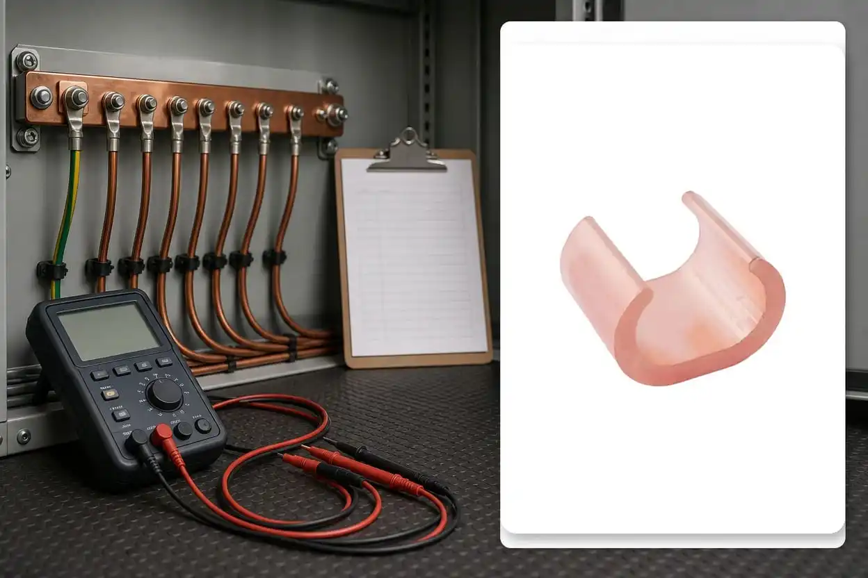
Inspection records should connect the installed clamp to its location, conductor IDs, tooling, photographs and approved documentation.
Inspectability should be decided during design. If a joint will remain visible, provide safe access and a consistent asset label. If it will be concealed, define hold points and evidence requirements before closure. The later the decision is made, the more likely the team will depend on incomplete memories.
For accessible installations, the maintenance plan can look for changes in routing, support, protection, visible condition, or signs of local heating identified by an approved inspection method. Trends and changes are more informative than undocumented snapshots.
For concealed installations, preserve location, product identity, installation photographs, and acceptance records in the asset system. A clear record may prevent unnecessary excavation or disassembly when a later system issue is investigated.
Use a structured review so that commercial pressure does not erase technical questions.
Confirm the system function: grounding, bonding, or conductor joining.
Confirm conductor identities and the exact connection geometry.
Request the CCT product drawing for the proposed arrangement.
Obtain approved installation and tool instructions.
Define environmental protection and accessibility requirements.
Require shipment and batch identity on handover documents.
State inspection hold points and required photographs.
Resolve every technical deviation before release for installation.
MINGXU’s verified product information supports describing CCT as a copper C-type clamp for grounding, bonding, and conductor connections. For a project approval, supplement that starting point with exact drawings and installation evidence rather than extending the web description into unsupported specifications.
Physical fit is not proof of compatibility. Stop and compare the connector, conductor, drawing, and tool instruction. If the intended combination is not documented, request confirmation before installation.
Concealment increases the need for control. Add a pre-closure inspection, photographs, and asset location record. Never use later inaccessibility as a reason to lower acceptance quality.
A test captures a condition at a moment in time. It may not reveal identity, geometry, or future mechanical risk. Keep both test results, where specified, and process evidence.
MINGXU identifies the CCT clamp for grounding, bonding, and conductor joining. The exact arrangement and installation requirements should be confirmed through the product drawing and project-approved documentation.
No. Selection should consider conductor material and construction, main-and-branch geometry, connection purpose, tool system, environment, and documentation. Diameter or apparent fit alone cannot confirm an approved combination.
Not by itself. It is one piece of evidence. Long-term confidence also depends on product identity, preparation, correct installation, strain control, environmental protection, and traceable records.
Request the exact model drawing, supported conductor combinations, installation instructions, tool requirements, material declaration, traceability information, and any project-required evidence. Do not fill missing specifications with assumptions.
A dependable C-type grounding connection begins with a defined function and ends with evidence that another person can audit. Treat conductor identity, geometry, tooling, corrosion control, and inspectability as one design chain.
If your project is evaluating CCT C-Type Copper Wire Clamps, share the conductor arrangement, application, installation environment, and documentation needs with the MINGXU team. They can use those inputs to discuss the appropriate product information and OEM/ODM support without turning an initial inquiry into an unsupported promise.
