
Views: 265 Author: Stephen Liu Publish Time: 2026-09-18 Origin: Site


Cable lugs for MCCB applications must fit the breaker’s actual terminal interface, the conductor, and the panel assembly process at the same time. MINGXU identifies the ACL series for MCCB use, but the series name alone does not establish dimensions, ratings, or installation settings. Panel builders should approve the connection from controlled breaker drawings, lug drawings, cable data, access studies, and a documented sample review.
The most important constraint is often the spatial envelope around the MCCB, not the nominal cable cross-section. A theoretically compatible conductor can still produce a poor assembly when the lug conflicts with a phase barrier, cover, terminal recess, or cable-support path. Designing outward from the breaker interface is usually more reliable than choosing a lug first and forcing the panel to accept it.

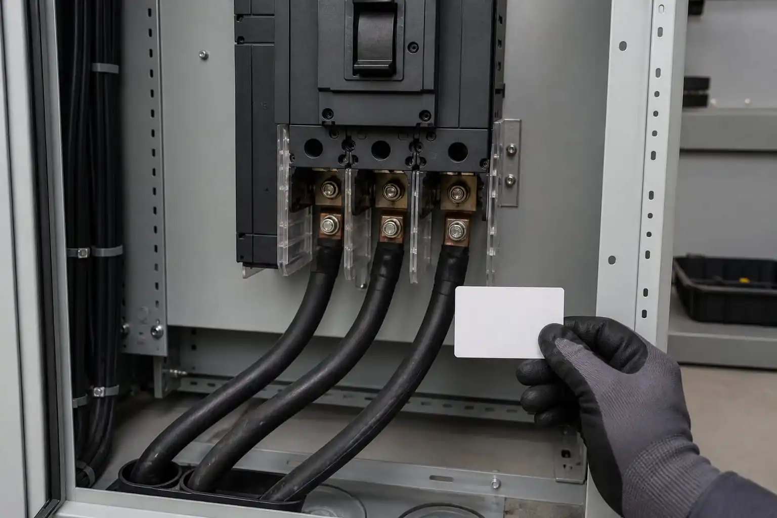
Illustrative MCCB interface review scene only. Final suitability depends on controlled breaker drawings, lug drawings and project documents.
Identify the exact breaker frame and terminal arrangement on the controlled bill of materials. Similar-looking MCCBs can present different landing faces, recesses, barriers, and accessory conflicts.
Review the equipment supplier’s current terminal drawing and installation information. Capture the connection face, fastening arrangement, permitted orientation, and any dedicated terminal accessory required by the equipment design.
Do not turn the ACL designation into an assumed dimensional standard. Its verified fact is MCCB use; the project must still establish the particular interface with drawings and approvals.
Record conductor material, construction, and project size from controlled cable data. Ask the lug supplier to identify the proposed variant and supporting document for that conductor.
Do not extrapolate from a nearby cable or an earlier panel. A cable description that looks familiar can conceal a different construction or project requirement.
Record the actual MCCB terminal identity, not a generic breaker description. Confirm the proposed lug form and orientation against the connection drawing.
Where an equipment accessory changes the connection face, include it in the configuration and approval record.
Model the termination with barriers, wireways, covers, supports, and nearby devices in place. A completed checklist should name the evidence behind every approval.
Keep the three decisions separate. Each can fail independently even when the other two appear acceptable.
Focus on the volume available after all mandatory parts are installed. An open enclosure during design can create a false impression of access that disappears after shrouds, ducts, covers, and supports are added.
Trace the conductor centerline from its support point to the MCCB. Include the barrel and transition area so the review captures where the cable begins to resist redirection.
Check opening and closing operations for doors or covers. A connection that fits while open may interfere with the finished assembly or later maintenance access.
Include phase dividers and terminal covers in the first layout, not as late accessories. Their geometry often determines palm width, orientation, installation sequence, and whether visual inspection remains possible.
Verify that the proposed lug does not require trimming, bending, or omitting a barrier. Such field work is a warning that the selected interface has not been engineered as a complete system.
Photograph the prototype with barriers installed and label the breaker, ACL sample, and drawing revision. This makes the review repeatable for production and quality teams.
Illustrative de-energized panel review scene only. Do not infer ACL dimensions, ratings or installation settings from this image.
Choose an approach direction that allows the lug to meet the terminal naturally. The final section of cable should not compensate for a poorly located duct or support through forced twist.
Place supports so cable forces are managed by the panel structure rather than transferred into the breaker terminal. Confirm that support installation and inspection remain possible after the connection is made.
Review service removal. A routing scheme that traps the MCCB or requires disturbing neighboring phases can increase future outage work even if initial assembly is possible.
Identify the required installation operations and draw their access envelopes. Consider the tool body, operator position, visibility of alignment features, and safe movement through the planned sequence.
Test the sequence on a representative panel section. Access should be repeatable for trained assemblers, not dependent on one expert using an undocumented workaround.
Link the work instruction to the approved lug and conductor combination. Where the project requires dies, settings, or fastening values, source them from controlled supplier and equipment documents rather than inventing them.
Proposed ACL variant and product drawing
Supported conductor description
MCCB terminal drawing used for the proposal
Identification and packaging method
Installation documentation required by the project
Sample and batch-document expectations
Send the breaker interface drawing, conductor data, enclosure constraints, and expected documentation with the inquiry. This gives the supplier enough context to respond to the real connection.
MINGXU’s website describes OEM/ODM services and traceability at company level. Translate any needed customization or traceability deliverable into an approved specification and purchase order instead of relying on broad marketing text.
Use the intended breaker terminal, cable, barriers, enclosure features, and tool when practical. A loose tabletop fit check cannot reveal enclosure or sequence problems.
Inspect the assembled interface from multiple angles. Confirm seating, absence of clashes, accessible hardware, stable cable routing, and restoration of all covers. Use the governing documents as the basis.
Record deviations and close them through drawing revision or explicit disposition. Never let a successful hand-fitted sample become permission for unrecorded production changes.
Match received ACL parts to approved documentation and purchase records. Keep unverified substitutions out of the line even when their external appearance seems close.
Inspect identification, visible condition, and layout-critical features under the project plan. Escalate missing drawings or ambiguous packaging before assembly consumes the batch.
Connect batch records to the panel serial or production lot where the project requires traceability. That link makes later investigation more useful than a stand-alone receiving report.
Identify the changed configuration item.
Compare the new and approved interface drawings.
Repeat affected conductor, terminal, and space checks.
Update the prototype or sample review when needed.
Release revised documents before production resumes.
Reopen the review when the MCCB, terminal kit, phase barrier, enclosure, cable, support, or routing changes. A small commercial substitution can alter the connection envelope.
Controlled change is less expensive than discovering a hidden interference during final inspection or commissioning. The approval record should make those triggers visible to purchasing and production.
A useful handover pack includes the released breaker and lug drawings, approved cable description, marked-up enclosure study, sample photographs, work instruction, inspection plan, and substitution restrictions. Give production one controlled location for these records so an outdated email attachment cannot quietly become the shop-floor reference.
The handover should also assign responsibility for open actions. Purchasing closes supplier-document questions, engineering closes interface decisions, production confirms the workable sequence, and quality defines evidence retention. Clear ownership prevents a technically sound concept from degrading between departments.
Before ordering volume quantities, review packaging and identification with receiving staff. The objective is to keep the approved ACL configuration distinguishable from similar parts from receipt through kitting and assembly. A strong technical selection can still fail if mixed inventory reaches the production line.
During the first production run, observe whether assemblers follow the demonstrated route and tool path. Record recurring hesitation, obstructed views, or requests to remove barriers. These signals are design feedback, not merely operator issues, and may justify a controlled layout improvement.
After release, use nonconformities and service findings to improve the checklist. The lesson should be expressed as a better drawing note, inspection point, packaging rule, or training step. Relying on verbal memory lets the same risk return with the next panel batch.
Extend the review to spares and service documentation. A replacement ACL part should retain the approved identity and drawing relationship; a description such as “MCCB lug” is too broad for configuration control. Maintenance instructions should preserve cable support and barrier restoration as well as the terminal connection itself.
If a service finding suggests overheating, looseness, interference, or cable movement, record the complete configuration before drawing conclusions. The investigation should identify the breaker terminal, ACL variant, conductor, routing, support, installation records, and surrounding components. This avoids attributing a system issue to a product name without evidence.
Use findings to refine the interface map and evidence request for the next build. A clearer photograph requirement, drawing overlay, label, kitting control, or assembly hold point often provides more durable prevention than a broad warning to installers.
The result is a disciplined MCCB connection process: the breaker interface sets the geometry, the conductor and route shape the assembly, controlled documents govern installation, and inspection records preserve what was actually built.
The MINGXU product listing identifies ACL cable lugs for MCCB use. Detailed dimensions, conductor ranges, current ratings, tightening values, and product certifications are not established by that fact and should be confirmed through project documents.
The lug must also match the breaker terminal and fit the enclosure with barriers, covers, cable supports, and tool access. Any one of those interfaces can reject an otherwise plausible selection.
A preliminary check can be useful, but final approval should use a representative assembled environment. Barriers, wireways, cable routing, covers, and installation sequence often expose the decisive constraints.
No. Company-level management-system statements should remain attributed at company level. They do not prove that a particular ACL lug carries a specific product approval.
For an ACL review, send MINGXU the exact MCCB terminal drawing, conductor description, panel-space constraints, cable approach, and documentation list. That evidence-first conversation can narrow the proposal and sample review without relying on guessed dimensions, ratings, or product certifications.
