
Views: 0 Author: Site Editor Publish Time: 2026-07-21 Origin: Site


Connecting aluminum cables directly to copper busbars introduces a serious engineering challenge for electrical contractors. You risk rapid galvanic corrosion and differential thermal expansion when these two incompatible metals meet. These physical reactions degrade the connection over time.
Incorrectly sized or poorly specified components inevitably lead to localized heating and severe voltage drops. As resistance increases, you face the real threat of catastrophic arc faults within your power distribution systems. Choosing the right termination hardware prevents these dangerous failures.
This article provides a technical, evidence-based framework for evaluating and specifying these critical connections. You will learn how to accurately size components, assess manufacturing quality, and implement robust installation practices for commercial and industrial grids. We focus strictly on mechanical integrity and long-term electrical reliability.
Precise sizing requires matching the lug’s aluminum barrel to the cable’s exact cross-sectional area (mm² or AWG) and the copper palm to the busbar stud size.
Friction-welded bimetallic joints offer superior mechanical strength and electrical conductivity compared to standard flash welding.
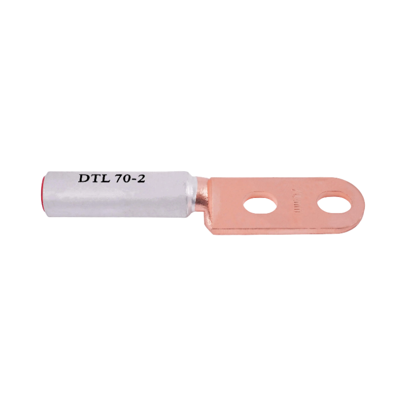
Anti-rotation requirements in high-vibration environments dictate the use of double-hole configurations (e.g., DTL-2).
Proper installation requires specific hexagonal crimping dies and the application of anti-oxidation compounds to ensure long-term reliability.
Electrical grids frequently mix materials to balance weight, conductivity, and structural needs. Utilities use aluminum for long cable runs. Switchgear manufacturers prefer copper for internal busbars. Joining them directly invites failure.
When moisture enters a direct joint between copper and aluminum, it triggers a destructive electrochemical reaction. The aluminum acts as an anode. It sacrifices itself to the copper cathode in the presence of an electrolyte. This rapid material degradation destroys electrical continuity. Moisture acts as the catalyst, and industrial environments supply plenty of it through ambient humidity.
True bimetallic cable lugs permanently isolate these metals. Manufacturers bond the copper and aluminum in a controlled factory environment. This creates a sealed transition zone. They prevent the ambient electrolyte from bridging the gap between the dissimilar conductors, entirely stopping the galvanic process.
Metals expand when heated and contract when cooled. Aluminum expands approximately thirty percent more than copper under the same thermal load. As current flows through your connection, temperatures naturally rise. The aluminum cable expands outward. If you use a rigid copper lug, it restricts this expansion. The aluminum deforms permanently against the harder copper constraint.
When the joint cools, the aluminum contracts. It does not return to its original shape. Standard single-metal lugs will loosen over time because of this physical reality. Engineers call this phenomenon "creep." Creep creates microscopic air gaps inside the barrel. These gaps lead to micro-arcing, increased electrical resistance, and further heat generation.
Many installers try using single-metal copper lugs paired with antioxidant joint compounds as a shortcut. This compromise introduces severe operational risks. You face unexpected system downtime, severe fire hazards, and immediate compliance failures during inspections.
Antioxidant paste alone cannot stop mechanical creep. You must accommodate the physical movement of the aluminum. Relying on a dedicated Bi-metal Crimp Lug for Power is the only mechanically sound way to ensure long-term network stability. It safely transitions the thermal properties from the aluminum cable to the copper busbar.
You cannot guess termination sizes. Engineering precise connections requires exact geometric matching between the cable, the lug, and the busbar. Errors here compound rapidly under high electrical loads.
Cable conductors come in solid, stranded, and highly flexible configurations. Each type occupies a different physical volume inside the lug barrel. A 120mm² Class B stranded cable has a different overall diameter than a 120mm² Class K flexible conductor. The air gaps between the individual strands change the required barrel volume.
Sizing components strictly by their rated current capacity is fundamentally flawed. You must match the sizing directly to the exact mechanical dimensions of your conductor. If you choose a barrel too large for the specific stranding, you risk under-crimping. The die will not compress the metal enough to form a solid mass. If you choose a barrel too small, you will break individual outer strands during insertion. Broken strands reduce the cross-sectional area and create high-resistance hotspots.
You must precisely match the hole diameter on the copper palm to the switchgear or busbar stud. Common industrial stud metrics include M8, M10, and M12 sizes. An oversized hole reduces the vital contact surface area between the palm and the busbar. An undersized hole forces installers to drill out the copper palm in the field. Field drilling ruins the structural integrity and creates dangerous burrs.
You also need to verify specific clearance requirements. In compact distribution blocks, phase-to-phase spacing tolerances remain extremely tight. Ensure the palm width does not exceed these physical boundaries. If the palm is too wide, it risks dangerous electrical arcing between adjacent phases during transient voltage spikes.
Medium and high voltage applications demand long-barrel lugs. The extended aluminum barrel provides enough surface area to accommodate multiple compressions. Double-crimping or triple-crimping distributes the mechanical stress evenly along the conductor. It maximizes the pull-out strength of the termination.
Many high-quality barrels feature integrated sight holes or inspection windows. These inspection points let you visually verify full cable insertion before you begin compression. Proper insertion depth guarantees the cable sits flush against the inner bimetallic junction. A shallow insertion leaves a hollow void inside the barrel, which collapses improperly under the crimping die.
The physical environment surrounding your electrical panels dictates the exact hardware configuration you need. Static environments require different solutions than dynamic, vibrating machinery.
Single-hole connections work best for standard, static power distribution panels. They fit perfectly where termination space remains heavily restricted. You use them on standard breaker landings and stationary grounding buses.
However, heavy-duty industrial environments introduce constant mechanical vibration. Transformers, industrial generators, and heavy motor drives shake continuously during operation. This intense vibration actively works to loosen standard single-hole connections over time. A loose connection arcs and burns.
You must specify a DTL-2 Double Hole Bimetallic Cable Lug for these harsh applications. The double-hole design provides essential anti-rotation properties. It locks the copper palm perfectly in place against the busbar. Two bolts prevent the lug from pivoting, maintaining strict torque limits over the equipment's entire lifespan.
Production methods define the ultimate reliability of the termination. Traditional flash welding often leaves microscopic air pockets along the seam. We call this defect weld porosity. These tiny voids throttle electrical flow and weaken the joint structurally.
We strongly advocate for friction-welded copper-to-aluminum joints. During friction welding, manufacturers spin the aluminum barrel against the copper palm at immense speeds. The friction generates intense heat, pushing the metals into a plasticized state. Heavy hydraulic pressure then forces them together.
This process creates a solid-state molecular bond. It operates just below the melting point, entirely eliminating weld porosity. The resulting seamless transition minimizes electrical resistance. It provides extraordinary mechanical strength, ensuring the joint will never snap during heavy hydraulic crimping.
You cannot determine the quality of a lug just by looking at it. You must rely on established material standards and rigorous testing frameworks. Substandard metals will fail under peak loads.
To guarantee safety, we establish strict baseline requirements for the raw materials. Reliable lugs utilize 99.9% pure electrical-grade copper for the palm section. The barrel must consist of at least 99.5% pure commercial aluminum. Any lower purity levels will severely degrade conductivity. Impure metals introduce unwanted resistance, transforming your termination point into a dangerous heater.
Evaluating compliance involves looking through rigorous testing lenses. You should always demand verified compliance with IEC 61238-1. This international standard governs compression and mechanical connectors for power cables. It subjects the components to grueling thermal cycling tests.
During these tests, laboratories heat the connectors to extreme temperatures and cool them down hundreds of times. They then subject them to massive short-circuit currents. Equivalent UL or ANSI standards also validate this extreme performance. Components passing these tests demonstrate true reliability.
We advise buyers to apply a skeptical evaluation check during procurement. Do not trust a superficial visual inspection of the weld line. A polished exterior often hides a weak, porous joint. Always request mill test certificates for the raw materials. Ask for independent thermal cycle test reports from the manufacturer. Verifiable data beats marketing claims every time.
Below is a quick reference framework outlining the critical criteria for verifying component quality:
Evaluation Area | Minimum Standard | Key Performance Indicator |
|---|---|---|
Copper Purity | 99.9% Electrical Grade | Guarantees maximum conductivity and resists surface oxidation. |
Aluminum Purity | 99.5% Commercial Grade | Provides optimal malleability for secure, crack-free crimping. |
Global Certification | IEC 61238-1 / UL 486A-486B | Passes 1000+ hours of extreme thermal cycling and short circuits. |
Data Verification | Independent Mill Reports | Eliminates the risk of installing counterfeit or substandard alloys. |
Even the highest quality lug will fail if your team installs it incorrectly. A bimetallic connection is only as reliable as its final crimp. You must control the installation process meticulously.
You must use standardized hexagonal dies specifically tailored for aluminum compression. Many installers mistakenly use indent crimpers. Indent crimps often crush and damage soft aluminum strands, breaking them internally.
Hexagonal dies apply uniform pressure from all six sides simultaneously. They compress the aluminum barrel and the internal conductor into a nearly solid, homogeneous mass. This eliminates all internal air voids. Always verify your hydraulic tool generates enough tonnage for the specific barrel size. An under-powered tool leaves the connection loose.
Aluminum oxidizes rapidly when exposed to ambient air. This microscopic oxide layer forms almost instantly. It acts as a powerful electrical insulator. You cannot ignore it.
You must wire-brush the exposed aluminum strands thoroughly to strip away this invisible barrier. Immediately after brushing, apply a high-quality electrical joint compound to the bare wire. This compound seals out oxygen and prevents the oxide layer from reforming. If your lug comes pre-filled with compound and capped from the factory, you can skip applying extra paste inside the barrel. You still must brush the cable.
You need clear post-installation success criteria to verify the connection before energizing the system. Implement the following rigorous checks for every termination:
Verify the complete absence of metal flash or sharp "ears" along the crimp edge. Ears indicate an oversized die or an over-crimped barrel.
Ensure the final crimp profile matches the die dimensions perfectly. You can measure this using standard calipers.
Check for proper crimp placement. Always start nearest the palm and work backward toward the cable entry.
Confirm you applied the exact recommended torque values on the busbar connection using a calibrated torque wrench.
Apply torque seal marks across the bolt head and copper palm to easily identify loosening during future maintenance inspections.
Finalizing your selection requires a methodical decision matrix. You must precisely intersect your exact cable cross-sectional area, the busbar stud size, and your environmental vibration conditions. Skipping any of these parameters compromises the entire installation.
We strongly recommend standardizing your procurement protocols around certified, friction-welded components. Doing so eliminates hidden points of failure across your entire distribution network. Specify double-hole configurations for any rotating machinery or high-vibration generator connections to maintain mechanical stability.
Implement mandatory tooling checks today. Ensure your installers use precise hexagonal dies for every termination. We prompt engineers and procurement managers to consult technical catalogs immediately. Request spec-matching assistance from qualified manufacturers to protect your grid from preventable thermal failures.
A: No. Using a standard copper lug on an aluminum cable is a severe safety hazard and violates major electrical codes. Antioxidant paste only prevents immediate oxidation. It does not stop galvanic corrosion or address differential thermal expansion. The aluminum expands and contracts differently than the copper, loosening the joint over time. This inevitably leads to overheating, arcing, and potential electrical fires.
A: The choice depends entirely on your mechanical environment. A DTL-1 single-hole lug works perfectly in static environments like standard distribution panels. You specify a DTL-2 double-hole lug for heavy-duty industrial applications, transformers, or generators. The dual-bolt design provides exceptional mechanical holding power. It actively prevents the lug from rotating under constant heavy vibration.
A: You must always start your crimping sequence from the palm side of the lug and work your way backward toward the cable entry point. This technical standard allows the aluminum barrel to slightly elongate outward as you compress it. If you crimp near the cable entry first, you trap the metal. This causes internal strand damage and weakens the joint.
A: No. Because the flat palm of the lug consists of pure solid copper, you treat the busbar connection exactly like a standard copper-to-copper joint. You simply follow the standard torque guidelines provided by the switchgear or busbar manufacturer for that specific bolt size. Always use a calibrated torque wrench for final tightening.
