
Views: 0 Author: Stephen Liu Publish Time: 2026-09-03 Origin: Site


A cable lug overheats for exactly one physical reason: its resistance is too high for the current passing through it. Everything else — the seven root causes below — is just a different way of creating that excess resistance. Power dissipated in a joint rises with the square of current, so even a modest increase in connection resistance can create a meaningful temperature difference under full load.
This guide is organised the way a diagnosis actually proceeds: what you observe, which causes produce that observation, how to confirm each one, and what fixes it permanently rather than until the next inspection.
Before opening the joint, extract everything the symptoms offer:
One phase hot, others normal → a workmanship or component fault at that specific joint. Start at cause #1 below.
All phases warm equally → overload or undersized conductor, not a lug defect. Check the load current against design before condemning hardware.
Discolouration pattern: heat centred on the crimp barrel points to a crimp-side fault (causes 1–3); heat centred on the palm and bolt points to interface faults (causes 4–7).
Green or white powder at the joint is corrosion product — jump straight to cause #5.
A thermographic camera makes this comparison fast when the circuit is operating under representative load. Follow the site electrical-safety procedure and use properly rated instruments; never rely on touch as a diagnostic method. Temperature trend and phase-to-phase comparison are more useful than a generic threshold because enclosure design, ambient temperature, emissivity and load all affect the reading.
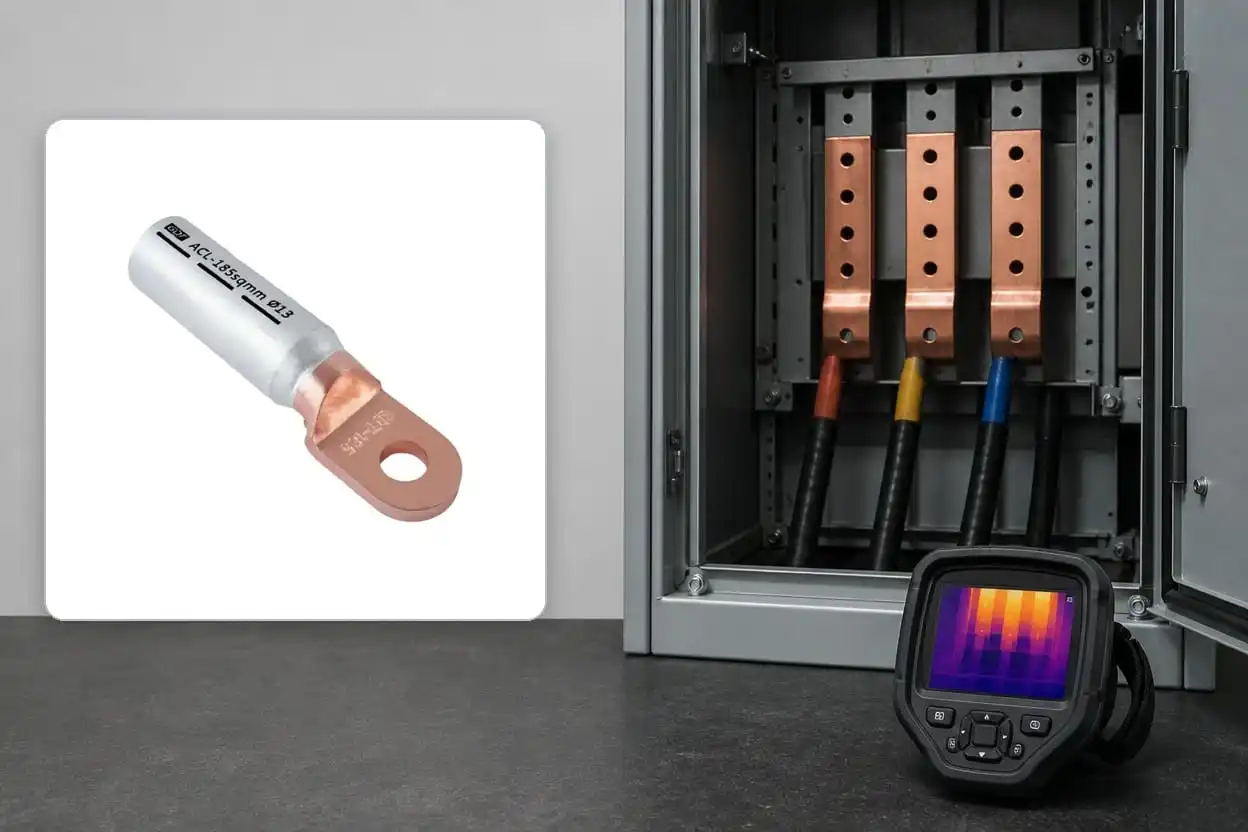
Compare similar loaded connections first, then isolate the circuit and inspect the crimp, palm and conductor before deciding the repair.
The most common crimp-side cause. A die one size too large, a hydraulic tool released before full pressure, or a missed crimp position leaves voids between strands and barrel wall. Current squeezes through fewer contact bridges; each bridge overheats.
Confirm: the crimp indent looks shallow, die flash is absent, or crimp positions don't match the barrel markings. A sectioned sample shows visible voids.
Fix: re-terminate with the die code stamped on the lug and a tool that completes its cycle. There is no repair for an under-compressed crimp — re-crimping over a bad crimp compounds the geometry error.
Aluminium strands re-oxidise within seconds of brushing. A barrel crimped without oxide-inhibiting grease — or with the factory grease wiped out by a well-meaning installer — traps insulating oxide film in the contact interfaces. Resistance starts marginally high, then climbs as micro-movement from thermal cycling grinds fresh oxide.
Confirm: history — aluminium conductor plus a barrel that arrived un-greased or was cleaned out. Resistance drifts upward across months of thermal surveys.
Fix: cut back and re-terminate: stainless-brush the strands, use a lug with factory-filled grease, insert immediately, crimp immediately. Minimise the delay between brushing, insertion and crimping so a fresh oxide layer does not reform before the joint is made.
A flexible Class 5 conductor forced into a barrel bored for compacted Class 2 sheds strands at the barrel mouth; a Class 2 conductor rattling in an oversized barrel never reaches full compaction. Both concentrate current.
Confirm: folded-back strands visible at the barrel entry, or the conductor spec sheet disagrees with the lug's bore rating.
Fix: re-terminate with a lug bored for the actual conductor class. Never trim strands to fit — each removed strand permanently removes cross-section at the joint.
The palm-to-busbar interface transmits current through microscopic contact points whose total area rises with clamping pressure. Under-torqued bolts leave too few contact points. Over-torqued bolts yield the palm, crush the tin plating, and relax within weeks — arriving at the same under-clamped state from the other direction.
Confirm: torque-check against the equipment manufacturer's table (not a generic chart). Look for plating extruded at the bolt-head perimeter — the over-torque signature.
Fix: clean both surfaces, replace deformed hardware, reassemble and torque the connection to the equipment manufacturer’s specification with the approved hardware and washer arrangement. Do not introduce a generic washer stack or maintenance interval that conflicts with the equipment instructions.
An aluminium lug bolted to copper bus, or an aluminium conductor crimped into a copper lug, forms a galvanic cell whenever moisture is present. The aluminium corrodes into non-conductive hydrated oxide, which both raises resistance and physically wedges the joint apart.
Confirm: white/grey powder at the interface, pitting on the aluminium side after disassembly, and the fatal design review finding: Cu and Al in direct contact anywhere in the current path.
Fix — permanent, not palliative: replace the improvised interface with a friction-welded bimetallic lug (DTL/ACL type). This moves the copper-aluminium transition into a controlled factory joint and provides the correct metal at each connection surface. Pastes or interface washers should not be treated as substitutes unless the complete connection system is specifically approved for that arrangement.
Loads grow. A feeder that matched the original design may later operate above its intended duty after plant additions, and the termination can become one of the first locations where the added thermal stress appears. The lug is the messenger, not the culprit.
Confirm: clamp-meter the actual load against the design current; check whether all phases run warm together.
Fix: resize the circuit. In the interim, verify the existing terminations are otherwise sound — an overloaded circuit with marginal joints is how small problems become outage reports.
Terminations near transformers, generators or reciprocating machinery accumulate micro-movement at the bolted interface. Fretting wears through plating, exposes fresh metal to oxidation, and gradually loosens hardware.
Confirm: location correlation (the hot joints are the ones on the vibrating structure), polished wear marks on palm or busbar, loose hardware on inspection.
Fix: restore the interface using approved replacement parts and the equipment manufacturer’s torque procedure, then address the mechanical path — flexible braids or loops between vibrating equipment and rigid busbar, cable cleats that stop conductor mass from working the joint.
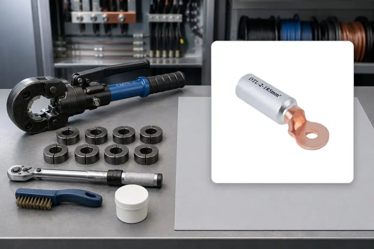
A permanent repair depends on the correct lug family, conductor preparation, matched die and equipment-specified bolt torque.
Never re-tighten a hot joint and walk away. Heat means resistance; resistance has a root cause among the seven above. Re-torquing a joint whose real problem is a dry crimp or corrosion buys weeks at best, while the underlying damage compounds. Open it, identify which failure signature you have, and fix that.
IEC 61238-1 load-cycle testing evaluates whether a connector maintains stable electrical and mechanical performance through repeated heating and cooling. Field joints follow the same principle: a correctly selected and installed termination should remain stable, while a marginal connection normally deteriorates rather than correcting itself.
How hot is too hot for a cable lug?
Two answers, and the comparative one is more useful. First compare the measured temperature with the cable, accessory and equipment ratings specified for that circuit; insulation limits vary by design and operating condition. Then compare like-for-like phases or parallel connections under the same load. A repeatable local temperature rise is grounds for investigation even when the absolute temperature remains below a nominal component limit.
Can a hot joint fix itself if the load drops?
The temperature drops; the damage does not. Oxide layers, relaxed clamping pressure and corrosion product all persist and resume compounding when load returns. Seasonal load profiles are precisely how marginal joints hide — cool all winter, cooking all summer — which argues for surveying at peak-load season, not whenever the thermography contractor has a free week.
Is infrared thermography enough, or do I need resistance measurements?
Thermography under meaningful load is the best wide-net screening tool available. Its limits: it needs line-of-sight (enclosed joints hide), load at survey time (a lightly loaded bad joint reads cool), and it flags symptoms, not causes. Micro-ohm measurements complement it — baseline readings at commissioning plus spot checks on flagged joints turn "this looks warm" into "this measures higher than comparable joints and has drifted from its commissioning baseline."
Should a discoloured lug always be replaced?
Treat visible heat discolouration as evidence that the joint needs to be isolated and assessed. Inspect the conductor, plating, contact surfaces and crimp before deciding the repair scope; replacement is normally the safer choice when heat has damaged the lug or conductor strands. Record the confirmed root cause as well as the location.
Do overheating problems differ between copper and aluminium terminations?
The physics is identical; the statistics differ. Copper joints tolerate process sloppiness better and fail more often at the bolted interface (causes 4, 6, 7). Aluminium joints concentrate failures at the crimp (causes 2, 3) and at mixed-metal interfaces (cause 5). Diagnostically, the conductor material tells you where to look first — it does not change what "good" measures like.
Most of the seven causes trace back to choices made before any tool touched the cable:
Type-tested hardware: lugs supported by applicable IEC 61238-1 test evidence and CE documentation where required, in declared material grades — T2/T3 copper and 1070-grade aluminium.
The right family per interface: copper lugs (SC/DT) for copper-to-copper, aluminium lugs (DL/AU) for aluminium-to-aluminium, friction-welded bimetallic (DTL/ACL) at every Cu-Al transition, 10 through 630 mm².
Matched tooling: the die system specified for the lug family, verified through a project-approved crimp qualification plan.
Baseline measurements: micro-ohm readings on major terminations at commissioning, so future surveys compare against data instead of guesswork.
If a thermal survey has just handed you a list of warm terminations and you suspect mixed-metal interfaces are among the culprits, MINGXU's engineering team can cross-reference your conductor and terminal schedule against the correct lug types — including friction-welded DTL/ACL bimetallic replacements for improvised copper-aluminium joints — with IEC 61238-1 documentation for every size. Send the survey findings and the cable list; the diagnosis half of the work is usually faster than the outage planning.
